
Introduction to Digital Stethoscopes and Maxim Integrated
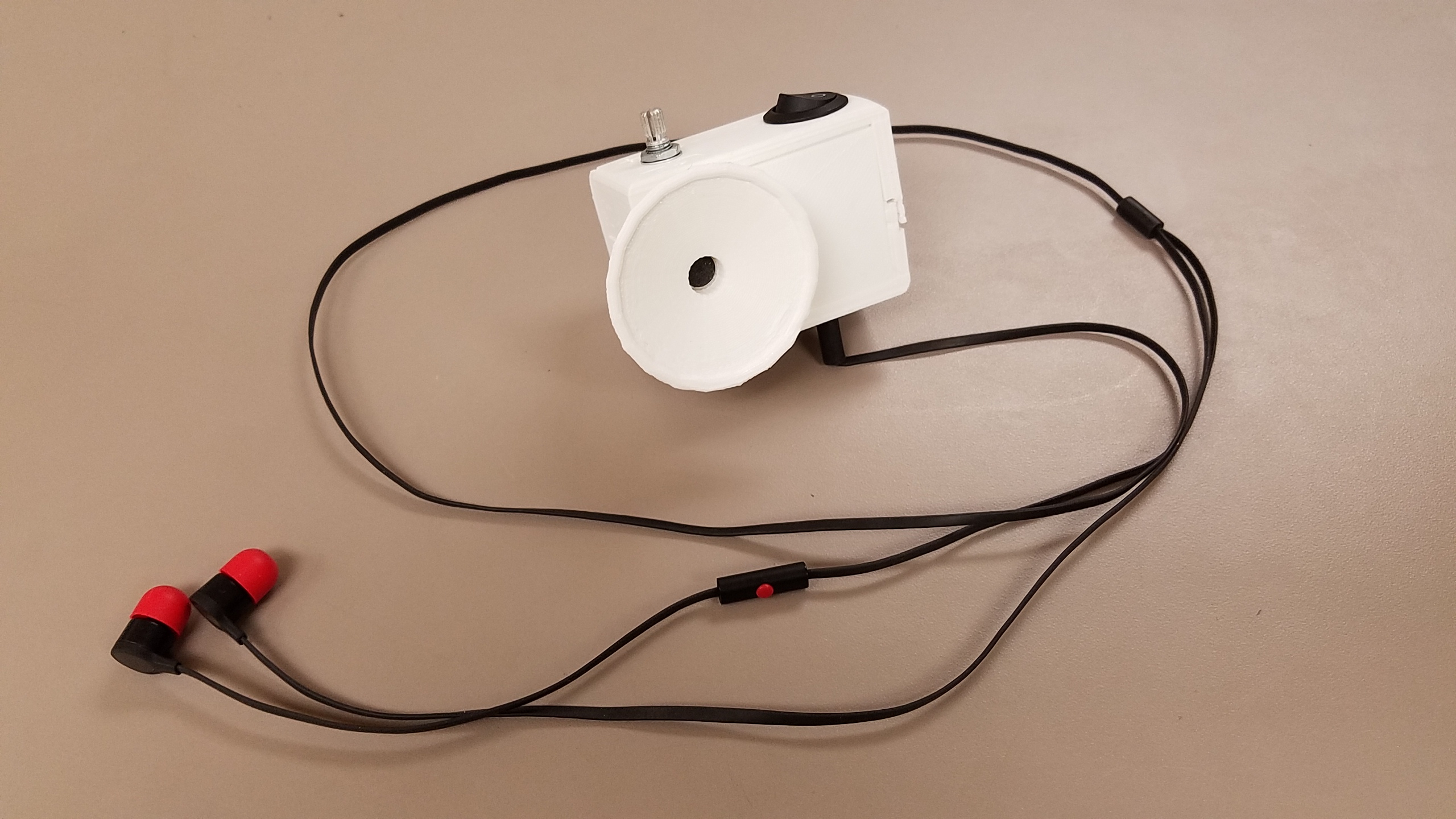
In this activity you will build an electronic stethoscope - ok its basically just an audio amplifier that uses physical amplification. We show you how to tes.
Electronic Stethoscope Appropedia The sustainability wiki
27 7 Download This instructable describes how you can make a low-cost electronic stethoscope using a high-quality MEMS microphone, and a high-gain low-noise OpAmp circuit. The design includes charging circuitry powered by a conventional micro-usb connector (from a phone charger or computer's USB port). The project requires the following parts:
Electronic Stethoscope Find That Noise! Nuts & Volts Magazine
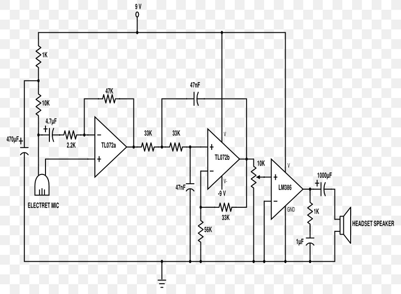
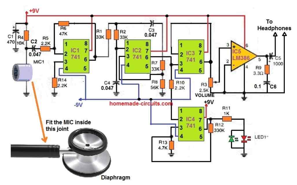
MIC1 is an assembly made out of a stethoscope head and electret mic. Cut the head off the stethoscope and use a small piece of rubber tube to join the nipple on the head to the mic. Be careful with the volume, as excess noise level may damage your ears. The + and - 9V may be supplied by two 9V batteries wired in series and tapped at the junction.
Digital Stethoscope ECE 4760
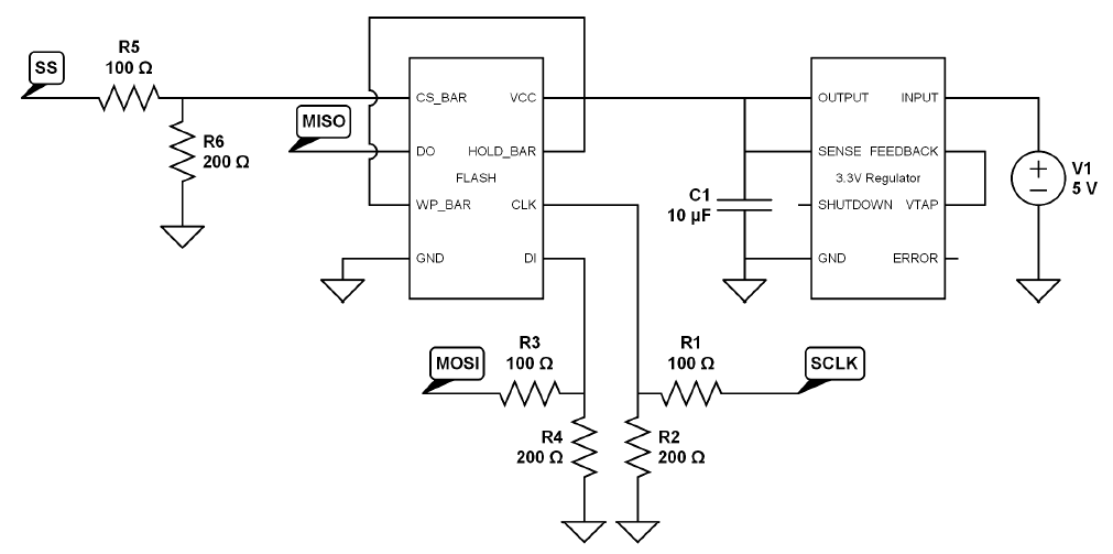
Electronic stethoscopes, like standard acoustic stethoscopes, only allow one listener, which .. Figure 2: Current electronic stethoscope circuit diagram with microphone input located on the left and audio outputs on the right Image Courtesy of: Spring 2011 Stethoscope Team.
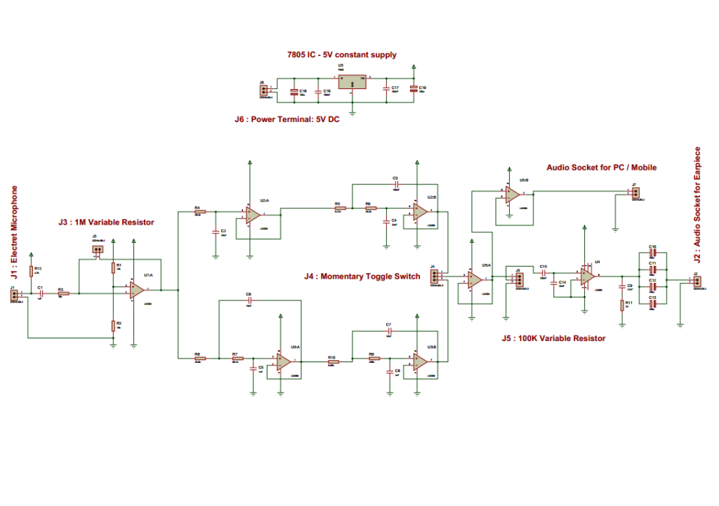
Full Circuit of Electronic Stethoscope
Our integrated circuits and reference designs for digital stethoscope complete with schematics, test data and design files feature and address several design requirements. Design requirements. Modern digital stethoscope designs require: Efficient power management solutions to provide longer battery life and high efficiency.

The Development Of Low Cost Electronic Stethoscope fyp_week 8 and 9 Pcb etching circuit
A circuit is requested that picks up sound vibrations from the diaphragm of the stethoscope and convert it to electronic signals that are then amplified and can be heard through a speaker loud enough that connecting to ears is not required and no sound is missed (even by less experienced practitioners).

Electronic Stethoscope How to Find the Best Electronic Stethoscope for You
The electrocardiogram (ECG) is a powerful and common screening tool for heart diseases. It is relatively inexpensive, non-invasive, and easy to use. However, it does have some limitations, one of which is the difficulty in detecting structural abnormalities in heart valves and defects characterized by heart murmurs [ 3 ].
Simple Electronic Stethoscope Circuit
The circuit was tested and validated using the stethoscope sensor and amplifier circuit after the software to capture the stethoscope output and generate the PWM signal was developed. The figure below shows the PWM signal and corresponding analog signal captured on an oscilloscope.. Several patents already exist for digital or electronic.
Circuit Diagram Stethoscope Electronic Circuit Schematic, PNG, 800x600px, Diagram, Area, Black
The electrocardiogram (ECG) is a powerful and common screening tool for heart diseases. It is relatively inexpensive, non-invasive, and easy to use. However, it does have some limitations, one of which is the difficulty in detecting structural abnormalities in heart valves and defects characterized by heart murmurs [ 3 ].

Tips For Choosing Good Electronic Stethoscopes Best Stethoscope Reviews
The main objective of this chapter is to provide the details of the design and the systematic approach towards developing an electronic stethoscope capable of capturing, amplifying, and processing sounds that are produced in identified internal organs for analyses and visualization through viable digital signal processing methodology.

Main components of the digital electronic stethoscope. Download Scientific Diagram
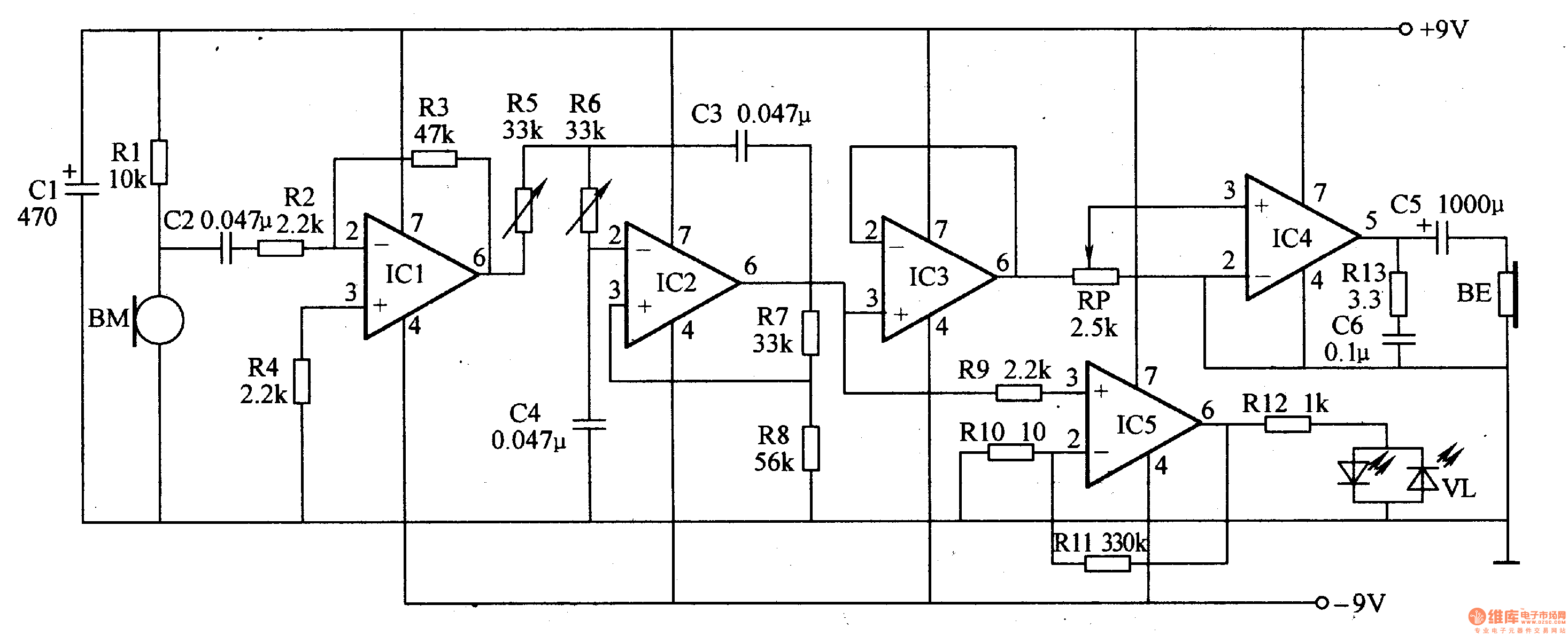
3. Simple Electronic Thermometer Circuit using Single LM324 IC. 4. How to Make a Heart Rate Sensor with Processor Circuit. 5. Heart Beat Pulse to Sound Converter Monitor Circuit. 6. Radon Detector Circuit. This intricately designed high precision electronic stethoscope circuit comprises two essential components: the microphone and the amplifier.
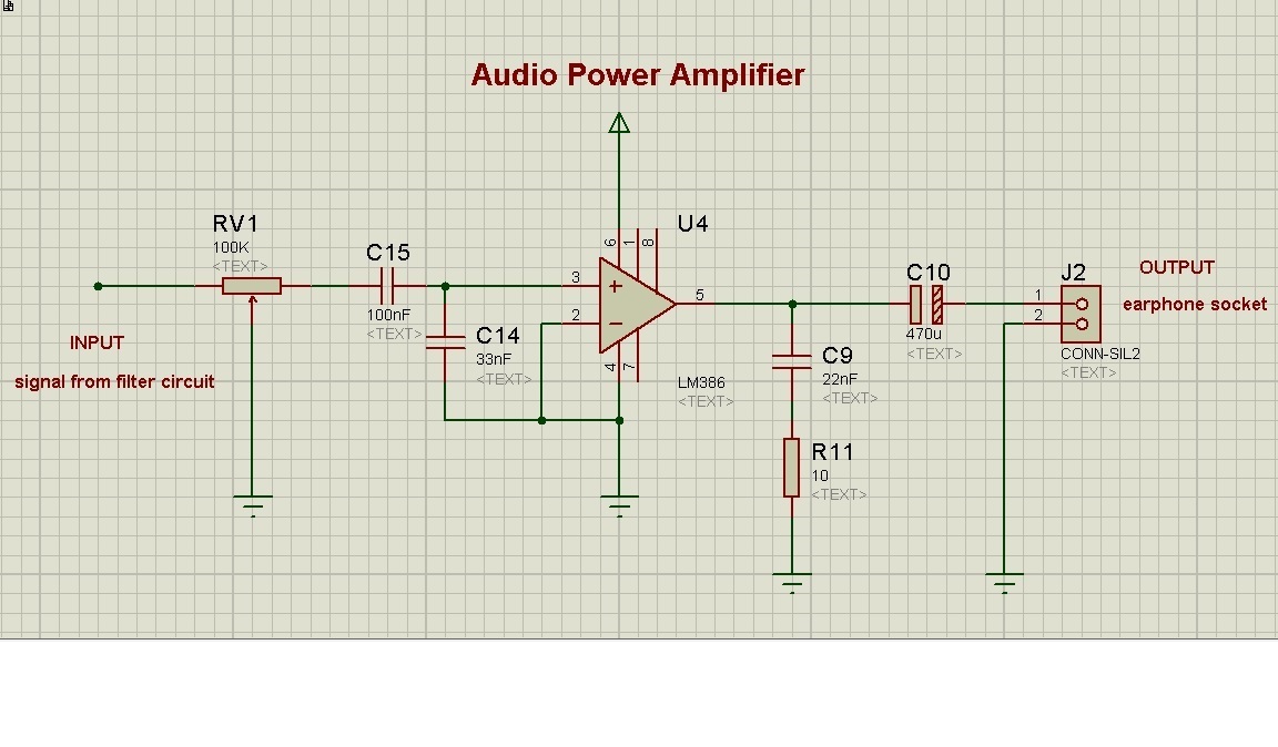
Power Amplifier for Electronic Stethoscope
In this paper, to resolve the above-mentioned issues, an electronic stethoscope was developed consisting of a traditional stethoscope with a condenser microphone embedded in the head to collect cardiopulmonary sounds and an AI-based classifier for cardiopulmonary sounds was proposed.
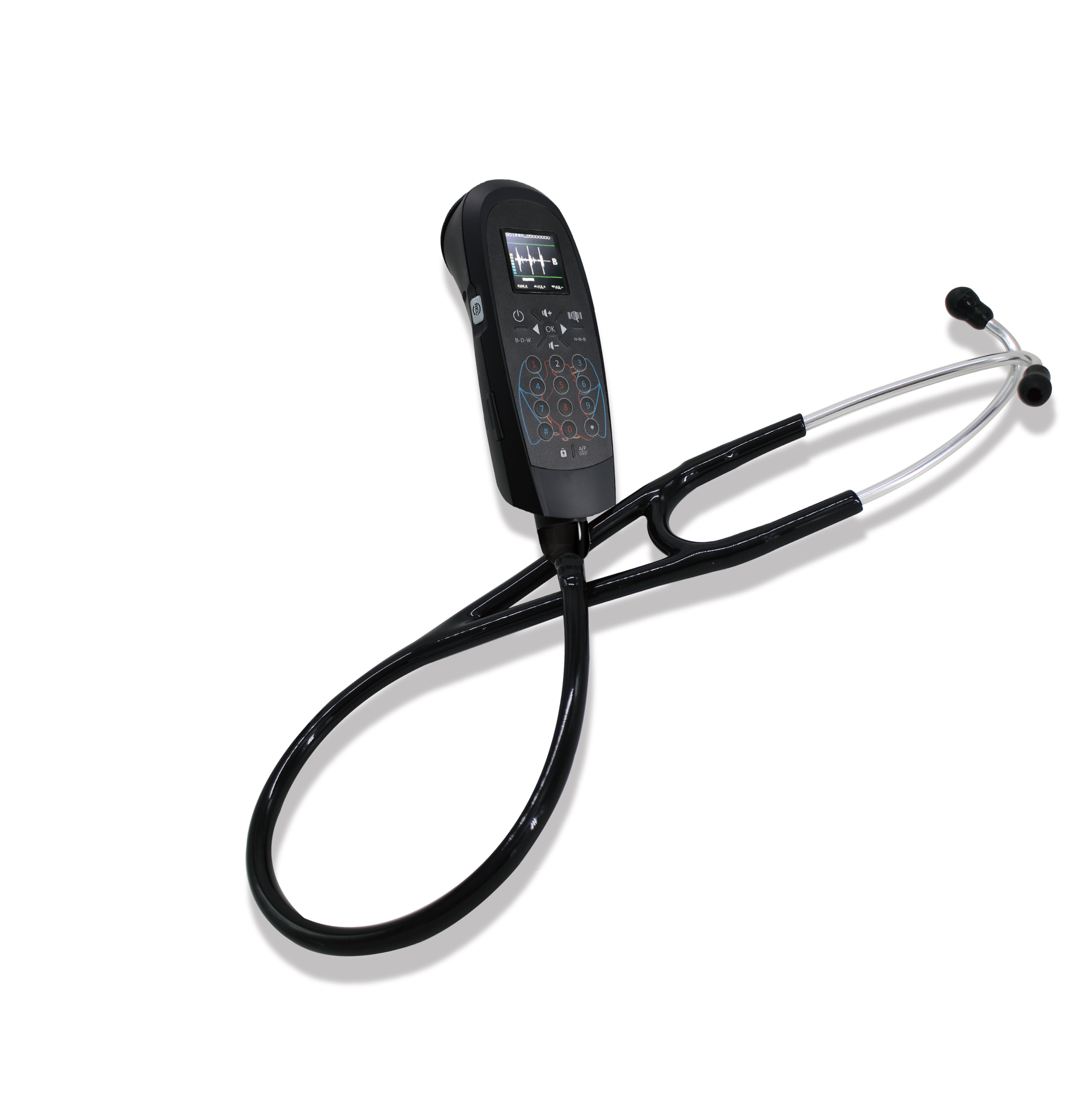
CaRDIaRT Electronic Stethoscope
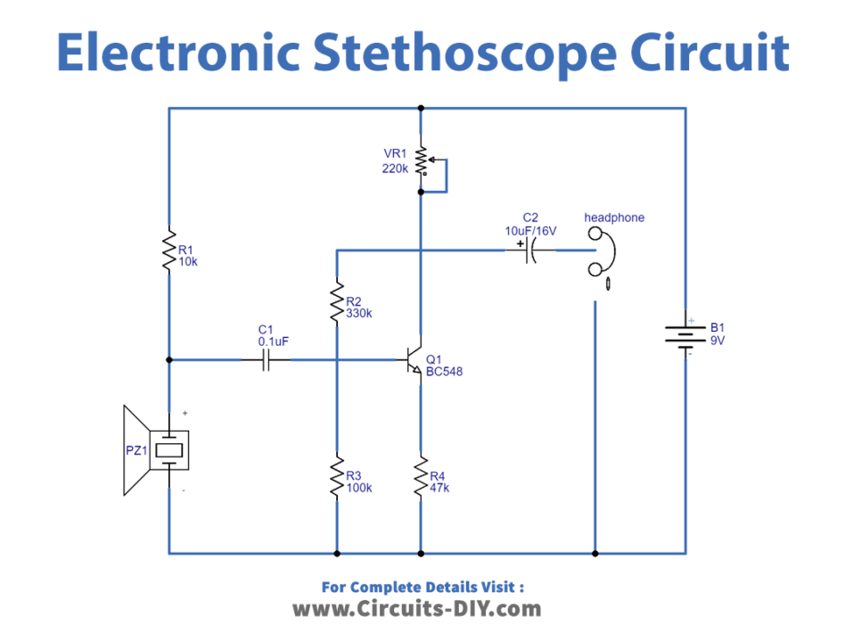
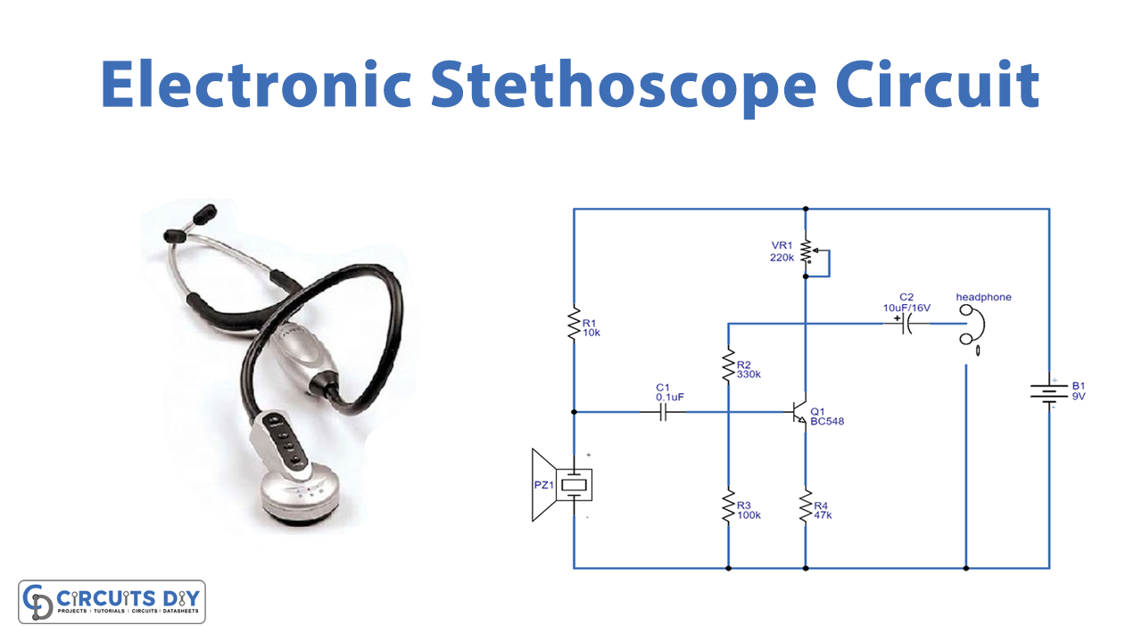
An electronic stethoscope is used to listen to your heartbeat and you would normally use a listening tube or stethoscope. This electronic stethoscope circuit uses a piezo sounder from a musical greetings card or melody generator, as a microphone.
voice amplifier circuit diagram
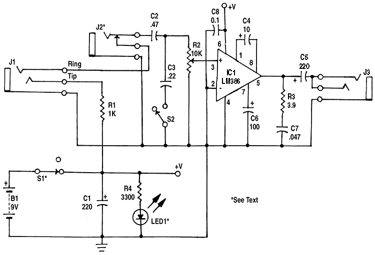
Figure 1. In the stethoscope amplifier, IC1 has a voltage gain of 200. In the electronic stethoscope circuit (shown in Figure 1 ), the LM386 operates at its maximum voltage gain of about 200; R2 is the volume control. (In circuits using the LM386, if C4 is omitted, the gain is about 20 and bypass capacitor C6 is not needed.
Making a Stethoscope Amplifier Circuit Homemade Circuit Projects
Circuit Diagram Working Explanation In this Simple Electronic Stethoscope circuit, we make a microphone out of piezo speakers. This transducer has a low-frequency response power capability of up to 100mV. This signal is incredibly weak. Therefore, to boost the signal, we must employ a high-impedance input impedance preamplifier.
Simple Electronic Stethoscope Circuit
A stethoscope, whether acoustic or digital, is used mainly to listen to heart and lung sounds in the body as an aid to diagnosis. Listening, or auscultation, has been done with acoustic stethoscopes for almost two hundred years; recently, electronic digital stethoscopes have been developed.
